Wiring Diagram For Photocell Sensor – Wiring Diagram is the graphical depiction of a intricate electric circuit. It represents the physical parts of the electric circuit as geometric forms, with the real power and link links between them as thin sides. It is really simple to draw a wiring diagram; you simply require to have a great understanding on various types of wiring and their functions. The Wiring Diagram is usually utilized in electric design to intend the placement of electric circuits. In Wiring Diagram, it is very vital to contend least one power wire and also one link wire, which are called as high-voltage line. The major function of these cords is to lug the electric existing.

As the Wiring Diagram is extremely complicated, so it is really essential to discover the different signs in Wiring Diagram. As you examine more about Wiring Diagram, you will find out that there are even more than hundred Wiring symbols made use of in a Wiring Diagram.
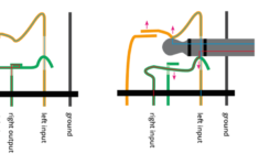
The Dashed Line: This is made use of to show the end of a selected connection factor in a Wiring Diagram. It indicates that the selected path is active or it will be connected to the terminal and will be in usage.

The Arrow: This is an additional essential Wiring symbol made use of to reveal the area of a connection point. The arrowhead is received the leading setting of the photographic diagram shows the active course for the electric present. It is adhered to by the non energetic links that are needed for the full circuit to function. The third arrow aware shows the numerous types of cables that are required for the complete circuit, to ensure that the Wiring Diagram can be completed.
The Radial Wiring Diagram: This is one more kind of Wiring diagram which is commonly made use of in electric and also electronic engineering field. The physical and electrical layout of the parts is set out in the Wiring diagram to make certain that just the needed links are made.

The Electric Circuit Diagram includes the following symbols. There is a line attaching the terminals. The color scheme of a Wiring diagram consists of mainly black, as it represents the common mode of operation for the electrical circuits. The other shades used are green, white, pink and cyan. The signs for switching over the connections on and off are shown in bold letters. On the other hand, the Wiring diagram signs that make a connection between one element and also one more are highlighted in pink.