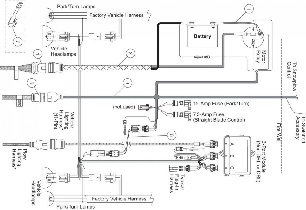
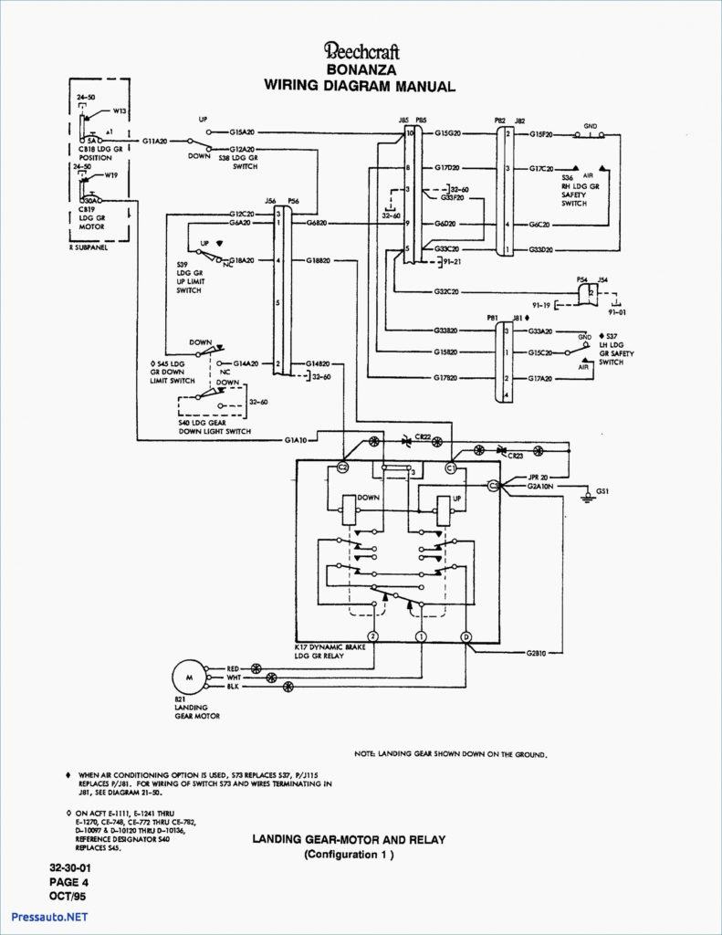
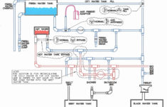
Fisher Plow Wiring Diagram – Wiring Diagram is the graphical representation of a complex electric circuit. It is extremely easy to attract a wiring diagram; you simply require to have a excellent understanding on various types of wiring and also their objectives. The Wiring Diagram is usually made use of in electric engineering to intend the positioning of electric circuits.
As the Wiring Diagram is very complicated, so it is very important to discover the different symbols in Wiring Diagram. As you research extra regarding Wiring Diagram, you will certainly find out that there are more than hundred Wiring signs made use of in a Wiring Diagram.
The Dashed Line: This is utilized to show completion of a picked connection point in a Wiring Diagram. The dotted line implies the active path. The light blue indicates the conductive path, while dark blue is the passive path. The rightmost 2 dashes represent the easy and also energetic courses, specifically. It implies that the chosen path is active or it will be attached to the incurable and also will certainly be in usage.
The Arrowhead: This is another important Wiring sign utilized to reveal the place of a link point. The third arrow in the photo reveals the various types of wires that are required for the complete circuit, so that the Wiring Diagram can be finished.
The Radial Wiring Diagram: This is another kind of Wiring diagram which is widely used in electronic and electric design field. This is utilized to outline the physical format of the part in circuits. The physical and electric design of the components is laid out in the Wiring diagram to guarantee that just the needed links are made. The Wiring diagram also shows the locations of the terminals for the links of the part. It is easier to draw the Wiring diagram in this manner.
The Electrical Circuit Diagram contains the following signs. The shade scheme of a Wiring diagram has primarily black, as it stands for the usual setting of operation for the electric circuits. On the various other hand, the Wiring diagram signs that make a connection between one element and another are highlighted in pink.
