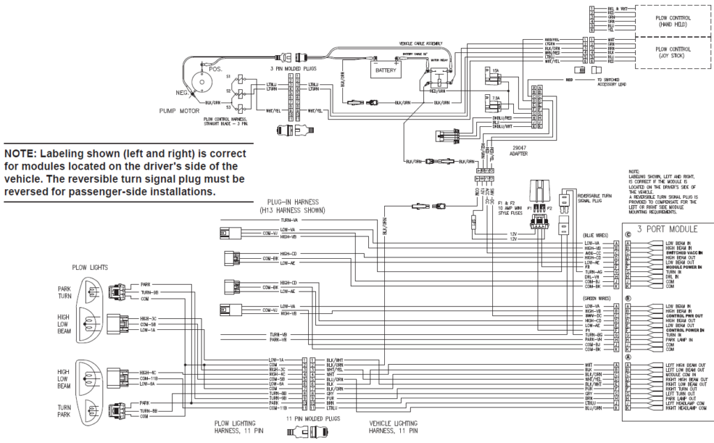
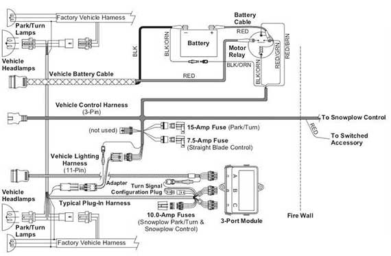
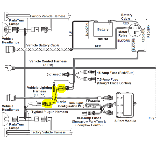
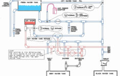
Fisher Plow 3 Port Module Wiring Diagram – Wiring Diagram is the visual depiction of a complicated electrical circuit. It is very easy to draw a wiring diagram; you just need to have a great understanding on various types of wiring and their objectives. The Wiring Diagram is generally utilized in electrical engineering to intend the placement of electric circuits.
As the Wiring Diagram is extremely complicated, so it is very important to discover the different icons in Wiring Diagram. As you research a lot more regarding Wiring Diagram, you will find out that there are more than hundred Wiring signs utilized in a Wiring Diagram.
The Dashed Line: This is used to reveal the end of a chosen connection point in a Wiring Diagram. It indicates that the chosen route is energetic or it will be linked to the terminal and also will be in use.
The Arrowhead: This is an additional important Wiring icon used to reveal the location of a connection factor. The arrow is received the leading setting of the pictorial diagram shows the active path for the electric existing. It is adhered to by the non active links that are needed for the complete circuit to function. The third arrowhead in the picture reveals the different types of wires that are needed for the complete circuit, to ensure that the Wiring Diagram can be finished.
The Radial Wiring Diagram: This is another sort of Wiring diagram which is widely made use of in electric and digital design field. This is utilized to outline the physical layout of the element in circuits. The physical and also electric format of the components is set out in the Wiring diagram to ensure that only the called for links are made. The Wiring diagram additionally shows the places of the terminals for the links of the component. It is less complicated to attract the Wiring diagram by doing this.
The Electrical Circuit Diagram includes the adhering to icons. The shade scheme of a Wiring diagram has mainly black, as it represents the usual setting of procedure for the electric circuits. On the other hand, the Wiring diagram signs that make a link between one element and one more are highlighted in pink.
