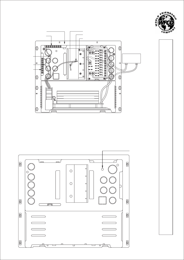
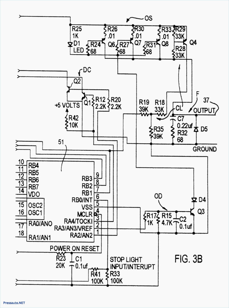
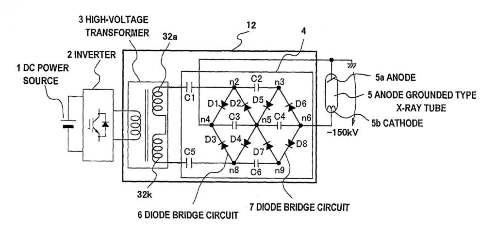
Wiring Diagram For Wfco 8955 Converter – Wiring Diagram is the graphical depiction of a complex electrical circuit. It represents the physical components of the electric circuit as geometric forms, with the real power and link links between them as slim sides. It is extremely easy to draw a wiring diagram; you simply require to have a excellent comprehension on different sorts of wiring and also their purposes. The Wiring Diagram is generally used in electrical design to prepare the positioning of electric circuits. In Wiring Diagram, it is really important to have at the very least one power cable and also one connection wire, which are called as power lines. The major function of these wires is to carry the electrical current.
As the Wiring Diagram is extremely made complex, so it is very essential to learn the different signs in Wiring Diagram. As you examine much more about Wiring Diagram, you will certainly discover out that there are even more than hundred Wiring signs made use of in a Wiring Diagram.
The Dashed Line: This is utilized to reveal the end of a selected connection point in a Wiring Diagram. The populated line suggests the energetic course. The light blue suggests the conductive course, while dark blue is the easy path. The rightmost 2 dashboards represent the energetic and also easy courses, specifically. It implies that the selected route is energetic or it will certainly be connected to the incurable and will remain in use.
The Arrow: This is an additional important Wiring icon made use of to reveal the area of a link factor. The arrow is shown in the top setting of the pictorial diagram shows the energetic path for the electrical existing. It is adhered to by the non active connections that are needed for the total circuit to function. The 3rd arrow aware shows the different kinds of cords that are needed for the total circuit, so that the Wiring Diagram can be completed.
The Radial Wiring Diagram: This is an additional type of Wiring diagram which is extensively used in electronic and also electric engineering area. This is utilized to outline the physical design of the element in circuits. The physical and also electric design of the elements is set out in the Wiring diagram to guarantee that just the called for connections are made. The Wiring diagram additionally reveals the locations of the terminals for the links of the element. It is less complicated to attract the Wiring diagram by doing this.
The Electric Circuit Diagram includes the following icons. There is a line connecting the terminals. The color pattern of a Wiring diagram has mostly black, as it stands for the common mode of operation for the electrical circuits. The various other colors utilized are green, white, pink and cyan. The signs for switching over the links on and off are shown in bold letters. On the other hand, the Wiring diagram symbols that make a connection in between one element and another are highlighted in pink.
