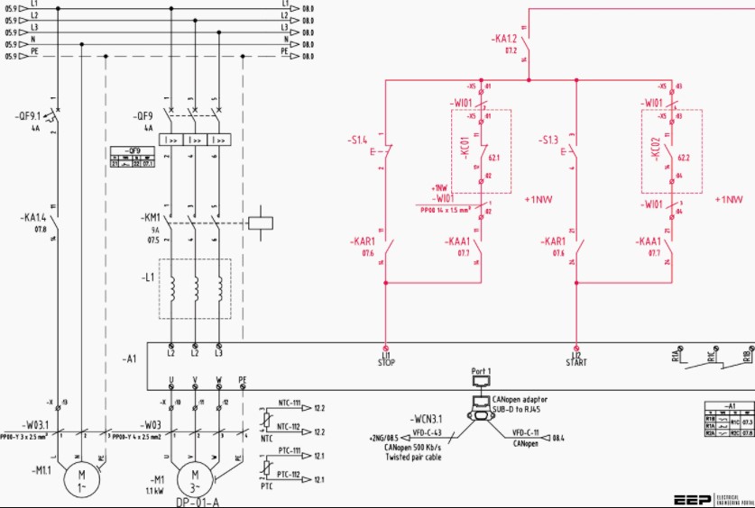
A wiring diagram is a simplified traditional pictorial representation of a complex electrical circuit. It presents the electrical elements of the circuit in simple shapes, with the electrical power and connection connections between the various elements as well as the location in space. The placement of each element within the circuit, as well as the location of any connecting terminals, are specified in the wiring diagram. They can be schematized by using different types of diagrams, or in physical diagrams or computer-assisted drawing (CAD) format.
The first electrical symbols to be used on a Wiring Diagram were the electric telegraph symbols. These consisted of a rectangle, whose corners were provided with electric lines, and whose middle was a circular disc. In some cases, a straight line was represented by a short vertical line through the top of the circular disc. This kind of Wiring Diagram allowed signals to be easily transmitted through several areas. These telegraph wires became very popular in the 1800s, especially when they were invented by Thomas Edison.

A more geometric Wiring Diagram represents electrical systems in three-dimensional form. There are no physical connections within the diagram, thus making it simpler to draw. The Wiring Diagram is usually drawn for a single electrical system. However, it can also be used to represent a number of systems, which are interconnected via wires, even if only in a visual representation.
There are several advantages to the use of Wiring Diagrams. One advantage is the accurate demonstration of wiring diagrams provides engineers and architects with a visual illustration of the physical location and functional sequence of electric circuits. With Wiring Diagrams, engineers and architects are able to visualize circuit behavior under real-life conditions. Wiring Diagrams can also be used in the design of power systems and control systems to ensure proper wiring for the protection of equipment and personnel.
The Wiring Diagram, however, has its limitations. When drawing Wiring Diagrams, the use of a visual graphically representation tool must be considered. The use of a ladder does not allow one to visually see the electrical symbols clearly. Also, a Wiring Diagram is drawn using a step-by-step approach that can not be as easily adapted for another system like a ladder because the electrical symbols would no longer be simple and easy to follow.
A Wiring Diagram is usually drawn as a top-down 3-D diagram. In this method, a user can see one circuit connection at a time and will not have to memorize and understand the symbols. This is a perfect tool for engineers and architects to create and analyze complex electrical systems. In Wiring Diagrams, a user is not restricted to a single circuit and can view all possible connections or combinations. The top-down Wiring Diagram can be rendered on many different levels such as a horizontal two-dimensional Wiring Diagram, a vertical two-dimensional Wiring Diagram, or a three-dimensional Wiring Diagram. Each one of these allows for the drawing and interpretation of more complex Wiring Diagrams.