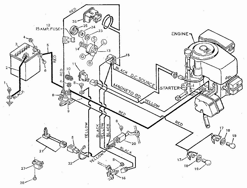
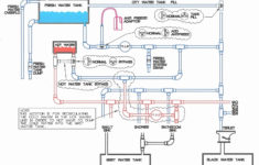
Ace Riding Mower Wiring Diogram – Wiring Diagram is the visual depiction of a complicated electrical circuit. It represents the physical parts of the electrical circuit as geometric forms, with the real power and connection links between them as thin sides. It is really simple to attract a wiring diagram; you just require to have a excellent comprehension on various kinds of wiring and also their functions. The Wiring Diagram is usually used in electric design to prepare the placement of electric circuits. In Wiring Diagram, it is extremely important to contend least one power cord and one link wire, which are called as high-voltage line. The major feature of these wires is to carry the electric present.
As the Wiring Diagram is really complicated, so it is really important to discover the various icons in Wiring Diagram. As you study more concerning Wiring Diagram, you will certainly find out that there are more than hundred Wiring icons used in a Wiring Diagram.
The Dashed Line: This is made use of to show the end of a selected link point in a Wiring Diagram. It suggests that the chosen path is active or it will certainly be linked to the terminal and also will certainly be in usage.
The Arrowhead: This is an additional vital Wiring symbol made use of to show the location of a connection factor. The arrow is displayed in the top placement of the photographic diagram reveals the energetic course for the electrical current. It is adhered to by the non energetic connections that are required for the total circuit to work. The third arrowhead aware reveals the numerous sorts of wires that are required for the full circuit, to ensure that the Wiring Diagram can be finished.
The Radial Wiring Diagram: This is another kind of Wiring diagram which is extensively made use of in digital and electrical design area. The electric and also physical design of the elements is established out in the Wiring diagram to make certain that just the needed links are made.
The Electrical Circuit Diagram contains the adhering to icons. There is a line linking the terminals. The color scheme of a Wiring diagram includes mostly black, as it represents the typical modus operandi for the electric circuits. The other colors used are green, white, pink and cyan. The icons for changing the connections on and off are displayed in strong letters. On the other hand, the Wiring diagram symbols that make a connection in between one component and an additional are highlighted in pink.

