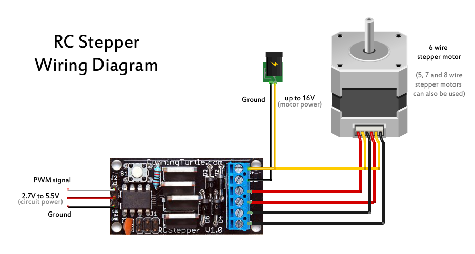
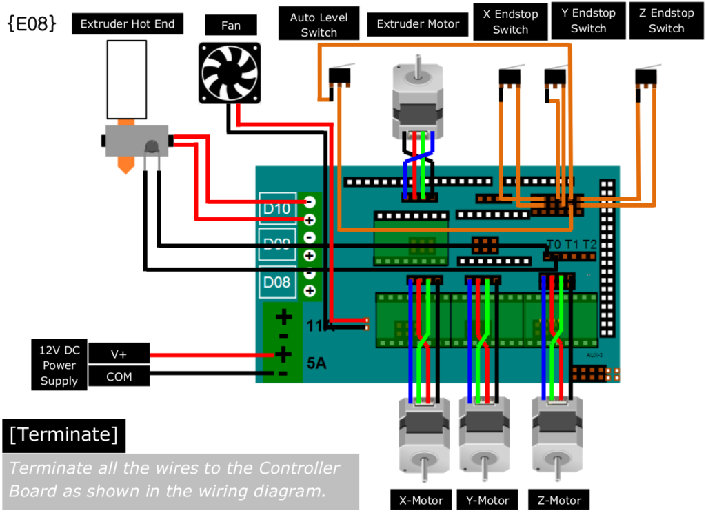
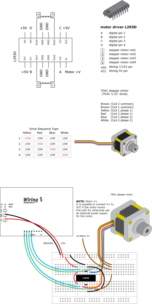
Stepper Motor Wiring – Wiring Diagram is the visual depiction of a intricate electric circuit. It stands for the physical parts of the electrical circuit as geometrical shapes, with the real power and also link connections between them as slim sides. It is very simple to draw a wiring diagram; you simply need to have a good understanding on different sorts of wiring and their functions. The Wiring Diagram is generally used in electrical design to intend the positioning of electric circuits. In Wiring Diagram, it is extremely crucial to have at least one power cord and one connection cable, which are called as high-voltage line. The significant function of these cables is to carry the electric existing.
As the Wiring Diagram is extremely made complex, so it is very crucial to discover the various signs in Wiring Diagram. As you examine much more regarding Wiring Diagram, you will certainly find out that there are more than hundred Wiring symbols made use of in a Wiring Diagram.
The Dashed Line: This is utilized to show the end of a selected link factor in a Wiring Diagram. It suggests that the chosen course is energetic or it will be attached to the terminal and also will certainly be in use.
The Arrow: This is an additional important Wiring sign made use of to show the area of a link factor. The arrow is shown in the leading position of the pictorial diagram shows the energetic path for the electrical present. It is complied with by the non energetic connections that are needed for the full circuit to work. The third arrow aware shows the numerous kinds of cables that are required for the complete circuit, so that the Wiring Diagram can be finished.
The Radial Wiring Diagram: This is another type of Wiring diagram which is commonly used in electrical and also digital design field. The electrical and physical layout of the elements is established out in the Wiring diagram to make sure that only the needed links are made.
The Electrical Circuit Diagram includes the complying with signs. There is a line connecting the terminals. The color scheme of a Wiring diagram contains primarily black, as it stands for the usual mode of operation for the electric circuits. The other colors used are green, white, pink and also cyan. The icons for switching over the connections on and off are shown in vibrant letters. On the other hand, the Wiring diagram signs that make a connection between one element and also one more are highlighted in pink.
