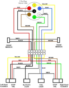
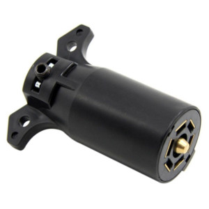
7-Pin Trailer Wiring Diagram With Brakes and also Accelerating Brake Lights
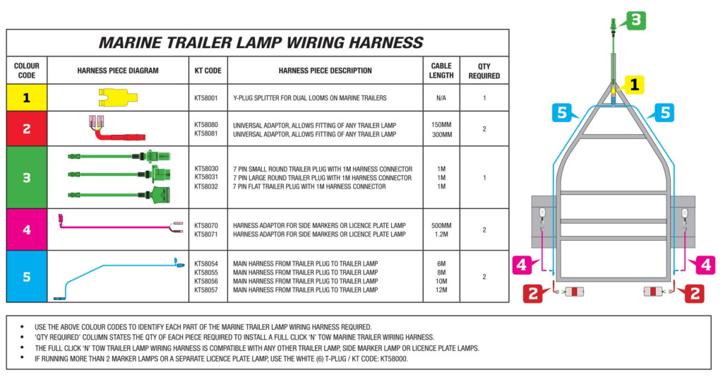
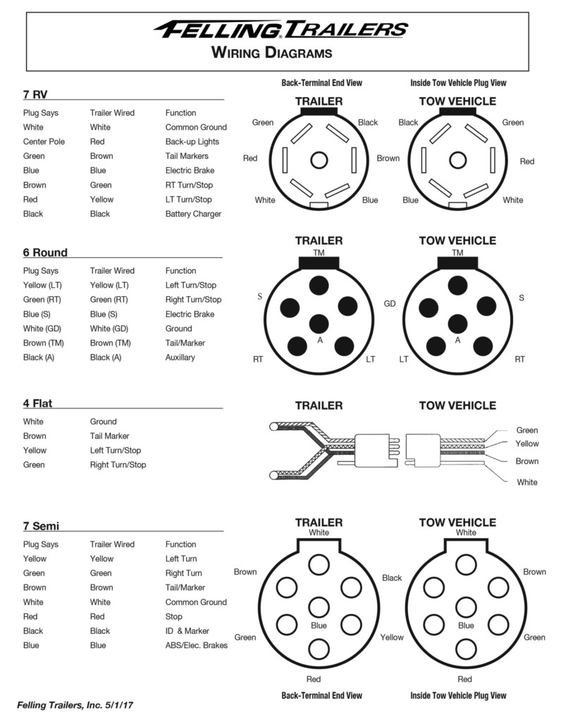
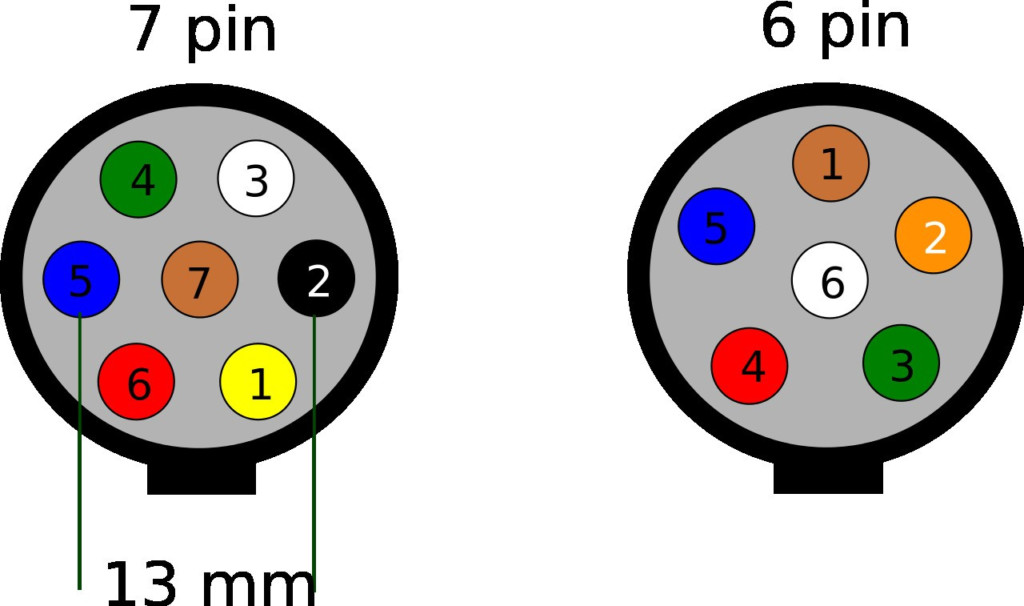
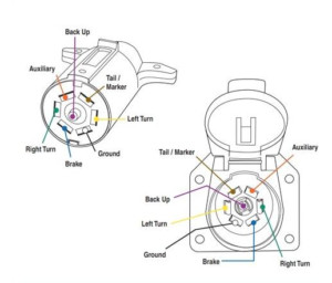
7 Pin Trailer Wiring Diagram – 7 pin trailer wiring diagrams as well as brake lights are a need for anybody operating a car that has both a trailer and also a vehicle . The safety and security of all persons on or off the roadway, as well as those running a motorized vehicle, depends upon recognizing how to operate the system that offers both the stopping and the acceleration. Oftentimes, it is just when the system is not functioning correctly that mishaps take place because chauffeurs and also passengers have the ability to expect the system’s procedure even when it is not working properly. This post provides information on the 7 pin trailer wiring diagram and brake lights.
You need to constantly have a full 7-pin trailer wiring diagram with you when you run a dual-cab vehicle, also if you never actually make use of the lorry due to the fact that you may need it while driving the truck to guarantee that the system that supplies for both braking and velocity is running appropriately. If you have a 2nd vehicle that has a traveler compartment, it is also extra essential that you have a full 7-pin trailer wiring diagram with brakes as well as an accelerator control so that when you apply pressure to the brake pedals, the system that supplies for both braking as well as velocity is working effectively.
An example of a 7-pin trailer wiring diagram with a brake controller and also accelerator control is as adheres to. Next, you will certainly need to connect a red-colored power wire to the white adapter on the chauffeurs’ side of the guiding column.
The next action in the 7-pin trailer wiring diagram with brakes and an accelerator control is to link the white and also red wires to their matching ports on the left side of the engine. Next, you will certainly need to link the environment-friendly cable to the environment-friendly port on the vehicle drivers’ side of the steering column. connect the purple cable to the green connection on the vehicle drivers’ side of the guiding column. This is complied with by connecting the last cable to a ground wire.
To conclude, you require to determine the 2 wires: the black as well as the white wires that go to the brake booster and also the left turn signal light. These are then linked to their corresponding connectors on the left side of your engine as well as a ground cable.
{ To conclude, there are just 3 steps in connecting your brakes and also left turn signal lights. You will have to identify which cord mosts likely to which port and make use of a red or eco-friendly cable to link the wires. This post has actually provided you with a quick review of just how to mount as well as make use of a 7-pin harness with brakes and an speeding up movement. If you are having problems or difficulties , it would be suggested to call a professional vehicle wiring professional for aid. | To end, there are just three actions in attaching your brakes and also left turn signal lights. You will certainly have to recognize which cord goes to which port and make use of a red or environment-friendly cord to link the wires.
