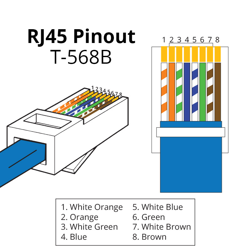
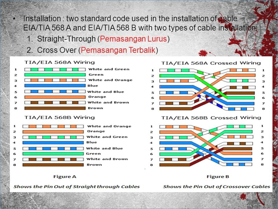
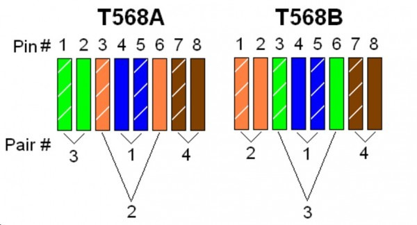
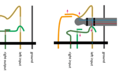
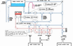
568b Pinout Wiring Diagram – Wiring Diagram is the graphical representation of a complex electric circuit. It is very easy to draw a wiring diagram; you just need to have a excellent understanding on various types of wiring and their objectives. The Wiring Diagram is generally utilized in electrical design to intend the placement of electrical circuits.
As the Wiring Diagram is very complicated, so it is really vital to learn the different icons in Wiring Diagram. If you wish to understand the signs conveniently, you can select any publication that has detailed details on electrical signs and their meanings. As you research more regarding Wiring Diagram, you will certainly learn that there are more than hundred Wiring signs utilized in a Wiring Diagram. A few of the significant Wiring signs are shown below:
The Dashed Line: This is made use of to reveal completion of a selected link factor in a Wiring Diagram. The dotted line suggests the active path. The light blue indicates the conductive course, while dark blue is the passive path. The rightmost two dashes represent the active and also easy paths, respectively. It means that the picked route is energetic or it will certainly be linked to the incurable and also will remain in usage.
The Arrowhead: This is one more essential Wiring icon utilized to show the area of a connection point. The 3rd arrow in the photo reveals the various types of cords that are needed for the complete circuit, so that the Wiring Diagram can be finished.
The Radial Wiring Diagram: This is an additional sort of Wiring diagram which is widely made use of in electronic and electrical design area. This is used to plot the physical layout of the part in circuits. The physical and electrical design of the elements is laid out in the Wiring diagram to make sure that only the required links are made. The Wiring diagram also reveals the areas of the terminals for the links of the element. It is easier to attract the Wiring diagram in this manner.
The Electric Circuit Diagram includes the complying with signs. There is a line attaching the terminals. The color pattern of a Wiring diagram contains mostly black, as it stands for the common modus operandi for the electric circuits. The various other shades used are green, white, pink and cyan. The symbols for switching the connections on and off are received vibrant letters. On the other hand, the Wiring diagram symbols that make a connection between one part and also one more are highlighted in pink.
