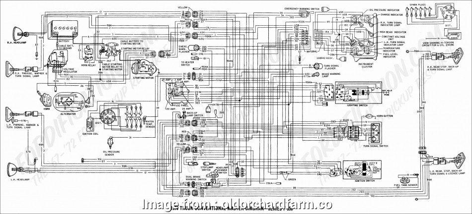
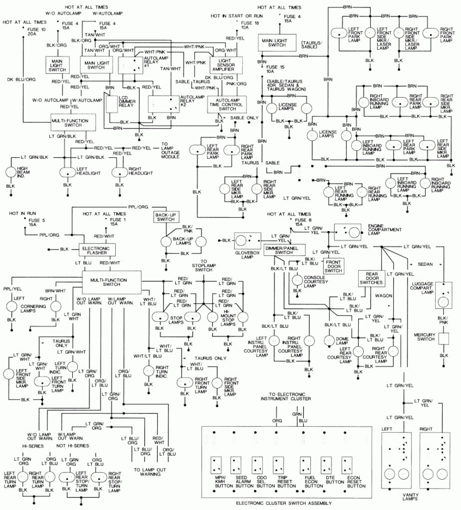
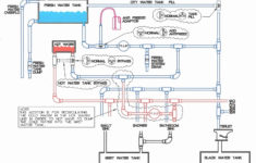
2006 F 250 Trailer Brake Control Wiring Diagram – Wiring Diagram is the graphical depiction of a complex electrical circuit. It represents the physical elements of the electric circuit as geometrical forms, with the actual power and link connections between them as thin edges. It is very easy to attract a wiring diagram; you just require to have a great understanding on various types of wiring and also their purposes. The Wiring Diagram is generally made use of in electric engineering to intend the placement of electrical circuits. In Wiring Diagram, it is extremely essential to have at the very least one power cord and one connection wire, which are called as high-voltage line. The significant feature of these cables is to bring the electric current.
As the Wiring Diagram is really made complex, so it is really crucial to discover the various symbols in Wiring Diagram. As you study extra concerning Wiring Diagram, you will locate out that there are even more than hundred Wiring signs utilized in a Wiring Diagram.
The Dashed Line: This is made use of to reveal completion of a picked connection point in a Wiring Diagram. The dotted line indicates the energetic path. The light blue shows the conductive path, while dark blue is the passive path. The rightmost two dashboards stand for the passive and also active paths, respectively. It means that the chosen route is energetic or it will certainly be attached to the terminal and will certainly be in use.
The Arrowhead: This is one more crucial Wiring icon used to show the place of a connection point. The arrowhead is shown in the leading position of the photographic diagram reveals the active path for the electrical current. It is adhered to by the non energetic connections that are required for the full circuit to work. The third arrowhead in the picture shows the different sorts of cables that are needed for the complete circuit, to ensure that the Wiring Diagram can be finished.
The Radial Wiring Diagram: This is an additional type of Wiring diagram which is commonly used in electronic and also electrical engineering field. The electrical and physical format of the elements is set out in the Wiring diagram to make sure that only the needed connections are made.
The Electrical Circuit Diagram consists of the complying with icons. There is a line connecting the terminals. The color pattern of a Wiring diagram contains mainly black, as it stands for the common mode of operation for the electric circuits. The various other shades utilized are green, white, pink and cyan. The icons for changing the connections on and off are received vibrant letters. On the other hand, the Wiring diagram symbols that make a connection in between one part and another are highlighted in pink.
